Reading P&ID Symbols and Abbreviations for the Pharmaceutical industry: A Step-by-Step Guide
By: Donagh Fitzgerald B.Prod Eng and Gerry Creaner B.Chem Eng. Last Updated: July 2024
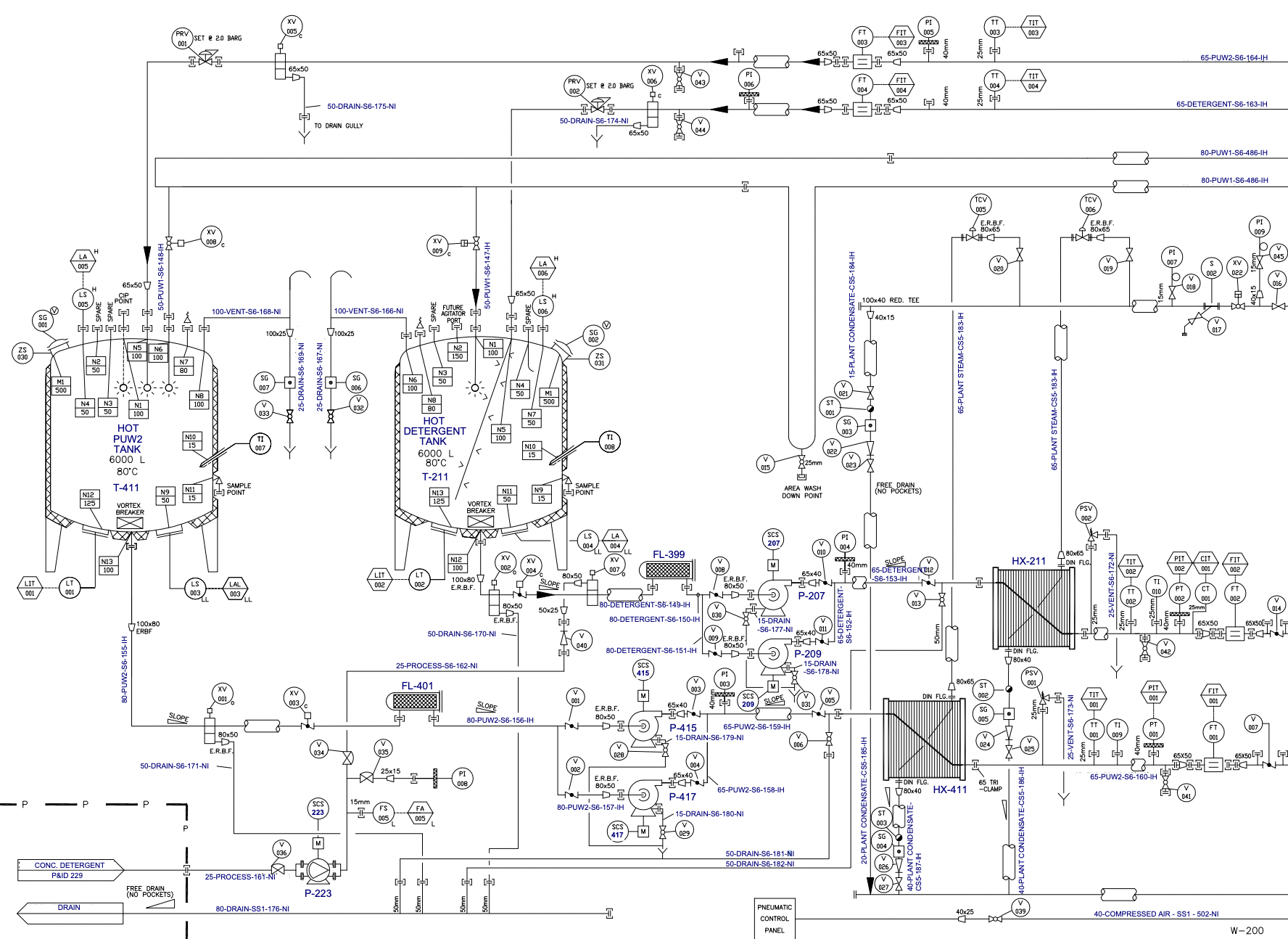
Piping and Instrumentation Diagram (P&ID) symbols are graphical representations used in Piping and Instrumentation Diagrams (P&IDs) to represent the various components of a process system such as pipes, pumps, valves, heat exchangers, instruments and tanks. These symbols help engineers and technicians understand and visualize the design and operation of a process.
They are designed to be easily recognizable and convey important information about the components they represent. In this guide, we will walk through the basics of P&ID symbols, notations, and abbreviations, and explain how to read them.
Important
P&IDs are living documents, and it is important to keep them updated as the process changes over time. Practice is key to understanding P&ID symbols, notation and abbreviation, and interpreting them correctly.
Equipment Validation Training Course
If you need to learn how to read P&IDs and qualify equipment systems within a pharmaceutical manufacturing plant, check out our Equipment Validation Training Course.
Table of Contents
Table of Contents
P&ID symbols can be broadly classified into 7 categories:
Piping Symbols
Examples include pipes, tubes, ducts, multi-line, separators, connectors, end caps, flanges, reducers, and coupling.

Pipe
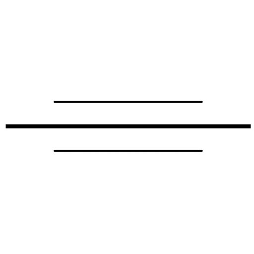
Jacketed pipe
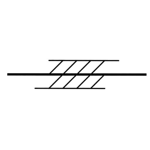
Thermally insulated pipe

Cooled or heated pipe

Covered gas vent
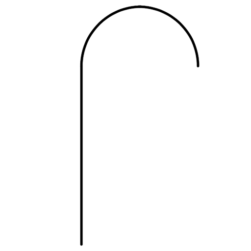
Curved gas vent
Flange

Butt weld

Reducer
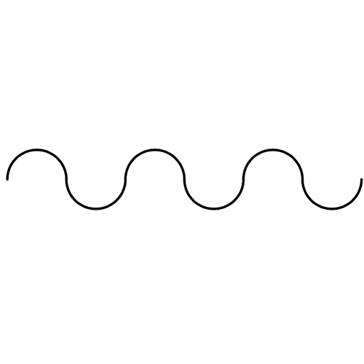
Flexible hose

Steam trap
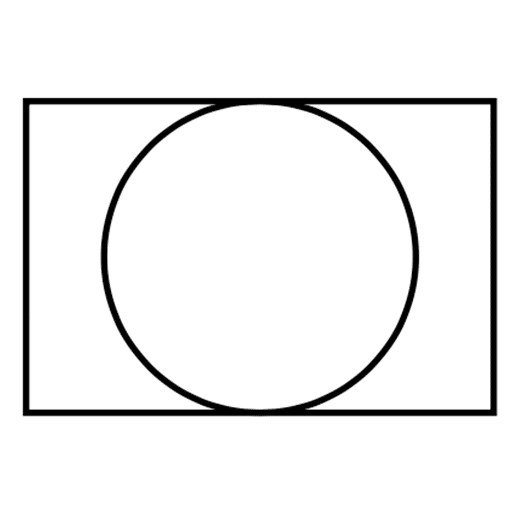
Viewing glass
Pump Symbols
Pumps are an essential part of the majority of industrial plants that need pumps. These pumps can be used for suction, compression, moving fluid, and also for pressure control. There are many p and id symbols for pumps.
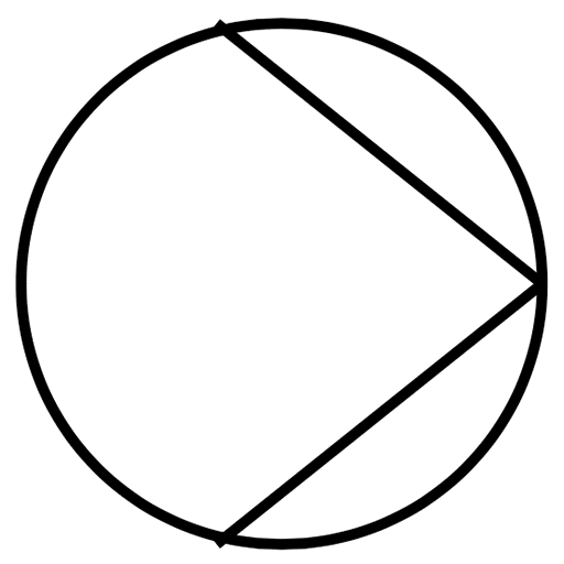
Pump
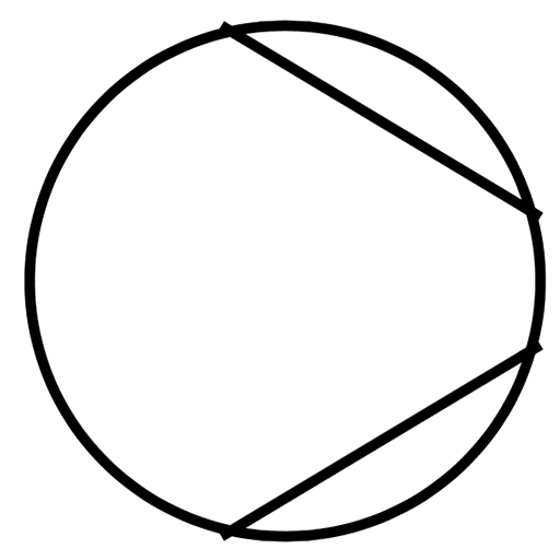
Vacuum pump or compressor

Centrifugal pump

Centrifugal pump

Centrifugal pump
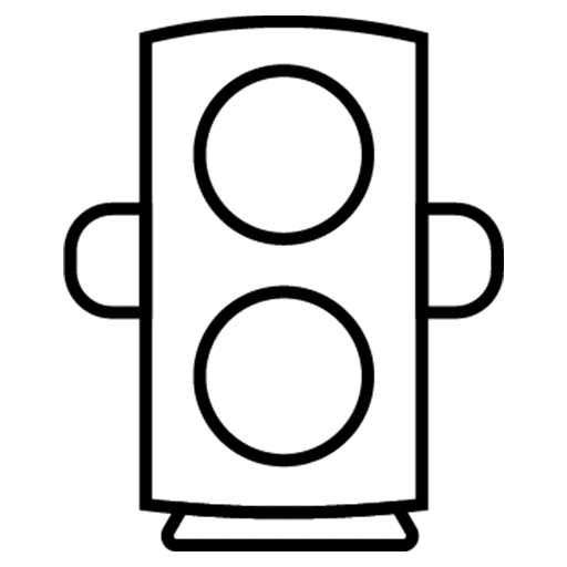
Gear pump

Screw pump
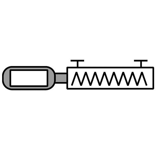
Screw pump
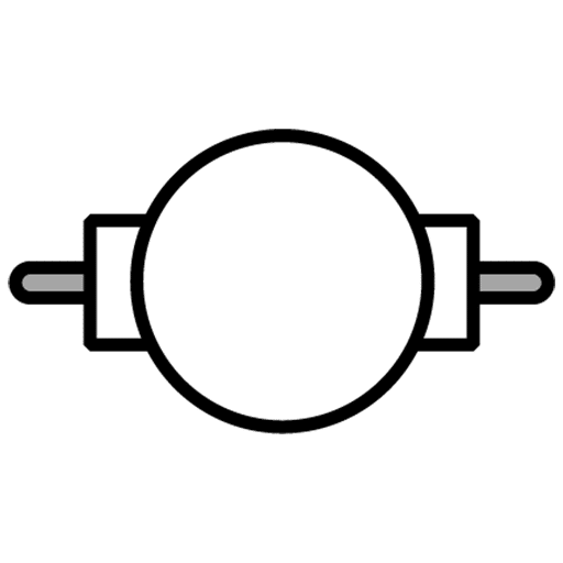
Vacuum pump
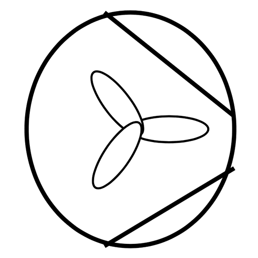
Fan
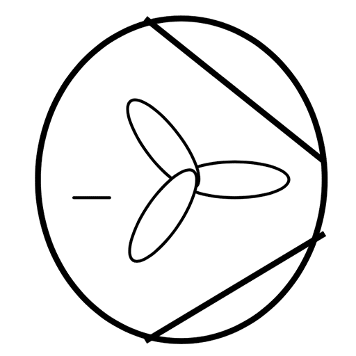
Axial Fan
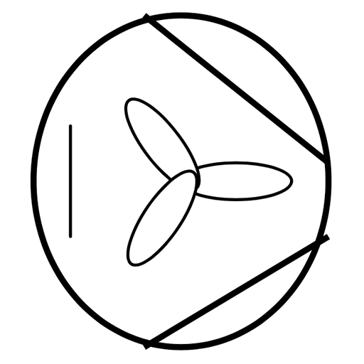
Radial Fan
Valve and Control Symbols
Represented by various shapes to indicate the type and function of the control device. Examples include valves, actuators, and controllers.
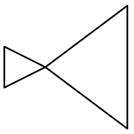
Pressure reducing valve
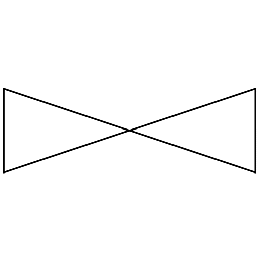
Valve
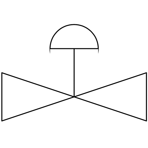
Control valve
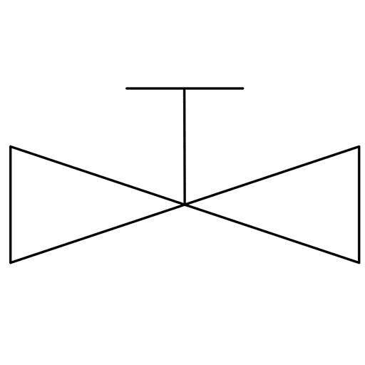
Manual valve
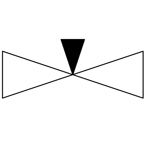
Needle valve
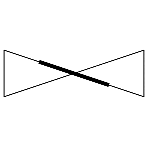
Butterfly valve
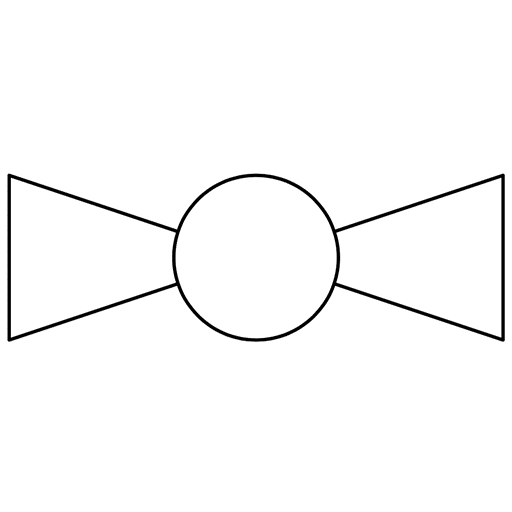
Ball valve
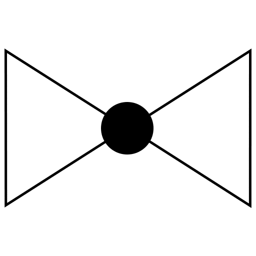
Globe valve
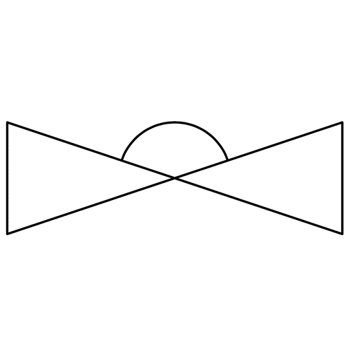
Diaphragm valve

Pressure regulating valve (PRV)
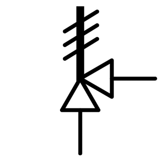
Pressure safety valve (PSV)
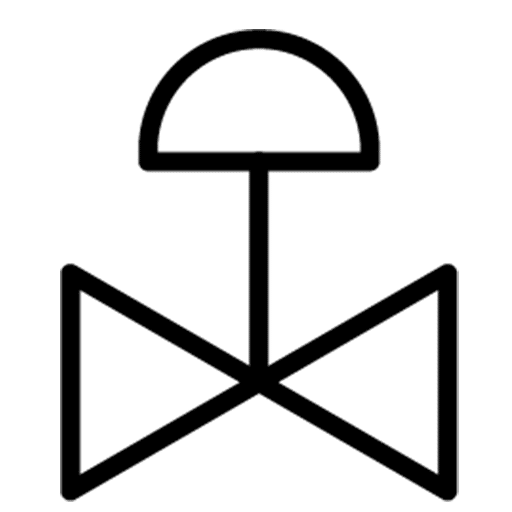
Temperature control valve (TCV)
Vessel Symbols
A vessel is used to store fluids or also be used to alter the characteristics of the fluid during storage. This includes tanks, cylinders, columns, bags.
Vessel
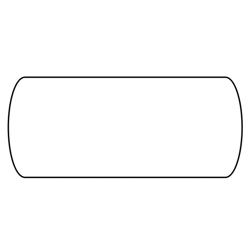
Pressurized horizontal vessel
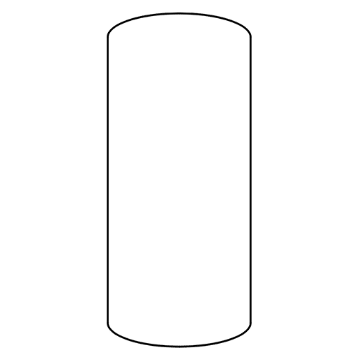
Pressurized vertical vessel
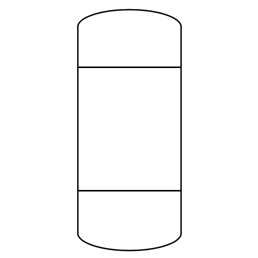
Reaction vessel

Column
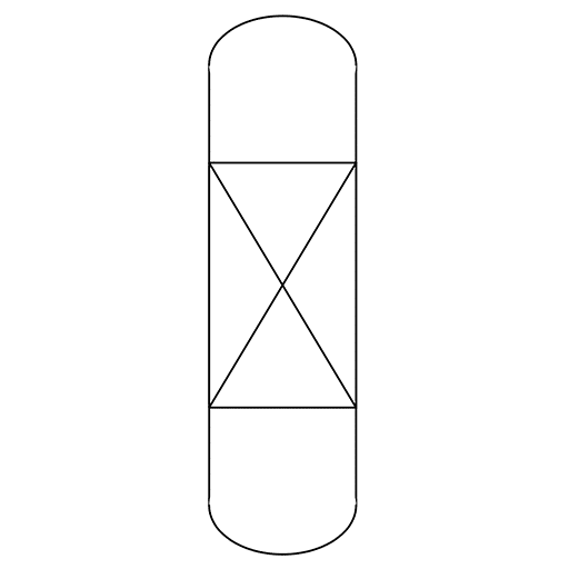
Packing column
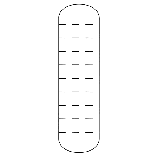
Tray column
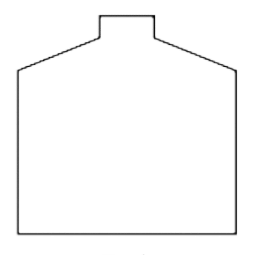
Tank

Open tank
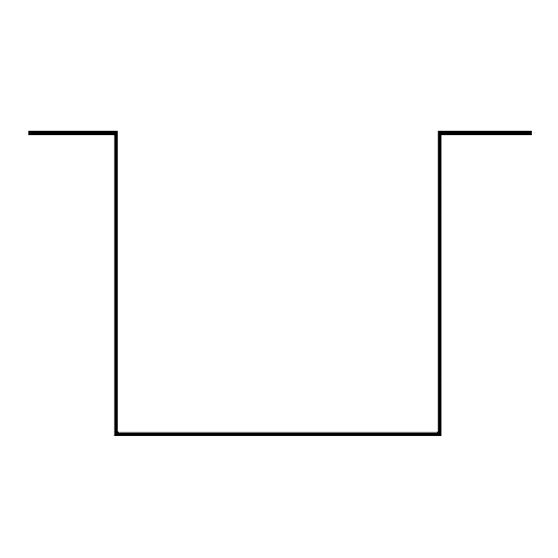
Open top tank

Closed tank
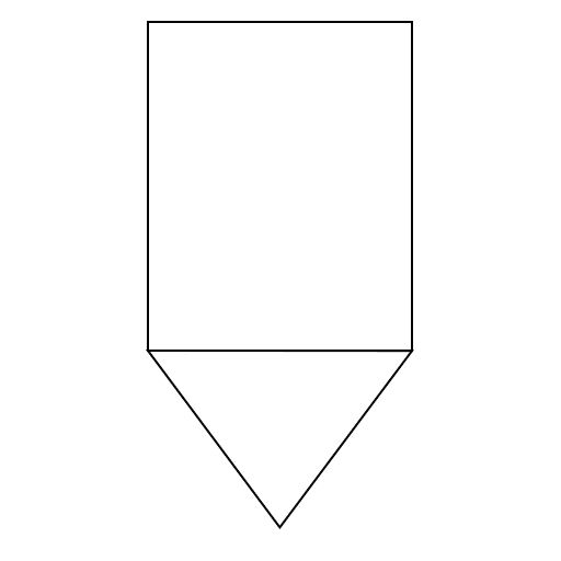
Bin
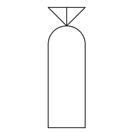
Bag
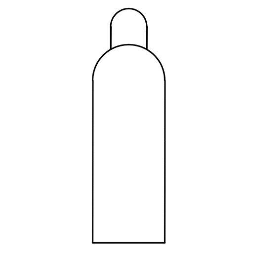
Gas bottle
Instrument Symbols
Pumps are an essential part of the majority of industrial plants that need pumps. These pumps can be used for suction, compression, moving fluid, and also for pressure control. There are many p and id symbols for pumps.
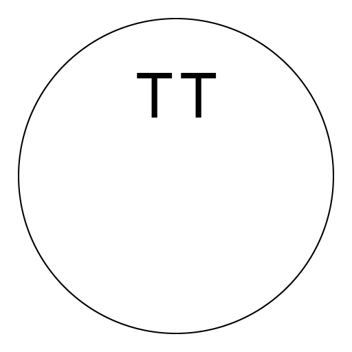
Temperature Transmitter
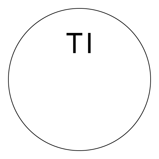
Temperature Indicator
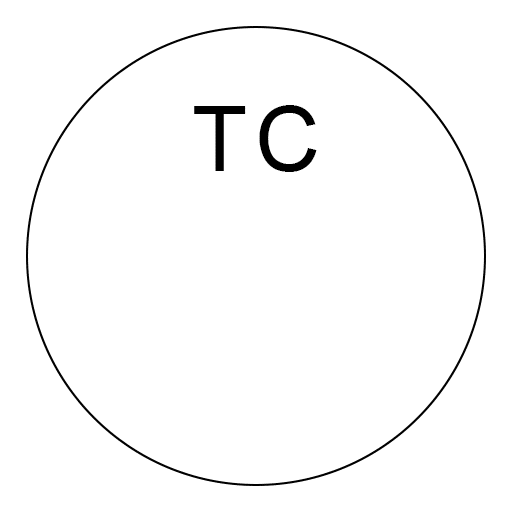
Temperature Controller
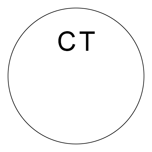
Conductivity Transmitter
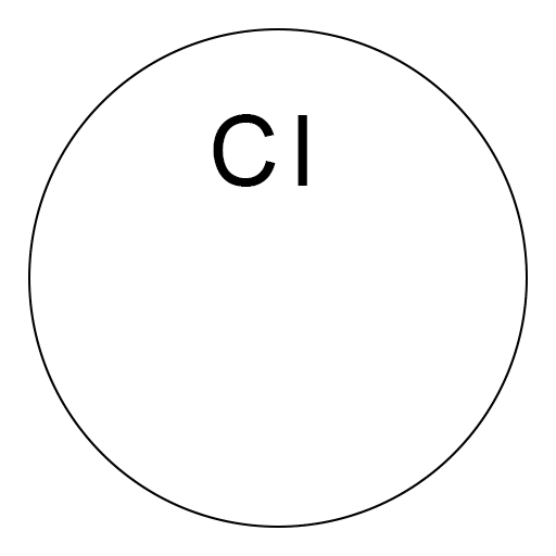
Conductivity Indicator
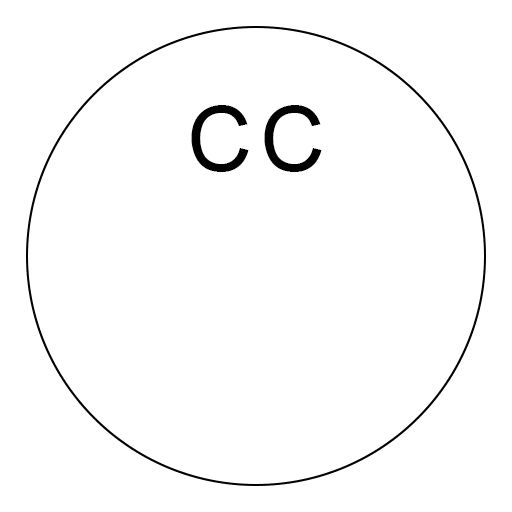
Conductivity Controller
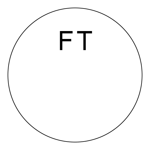
Flow Transmitter
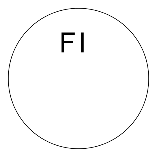
Flow Indicator
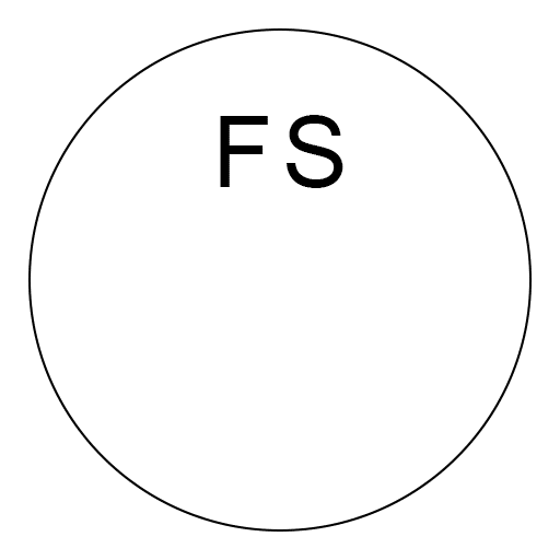
Flow Switch
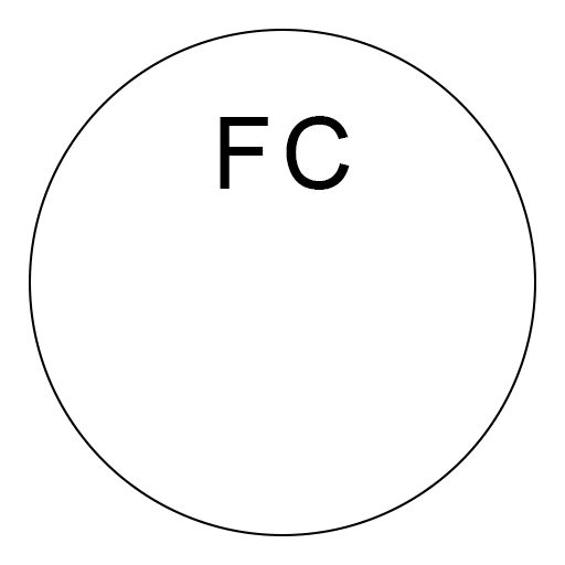
Flow Controller
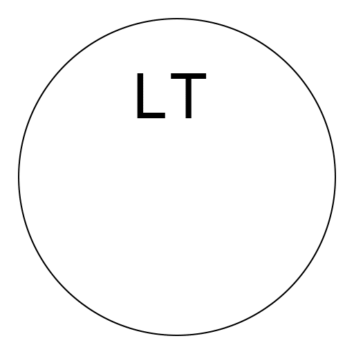
Level Transmitter
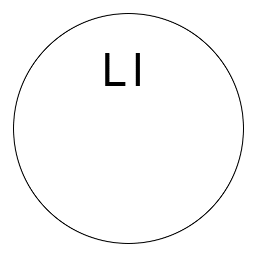
Level Indicator
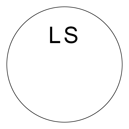
Level Switch
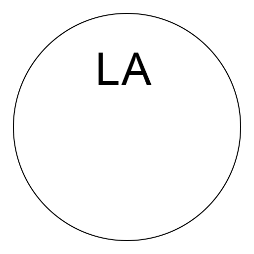
Level Alarm
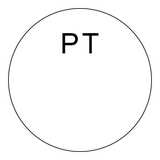
Pressure Transmitter
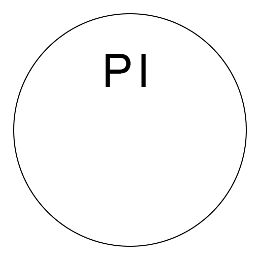
Pressure Indicator
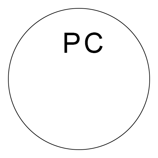
Pressure Controller
Equipment Symbols
Equipment is made up of items that don’t fit into other categories. This group includes hardware like reactors, dryers, turbines, vacuums, and other mechanical devices.
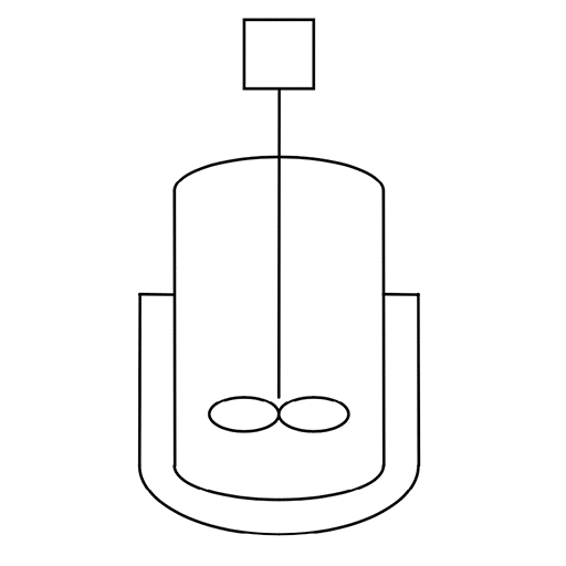
Jacketed mixing vessel
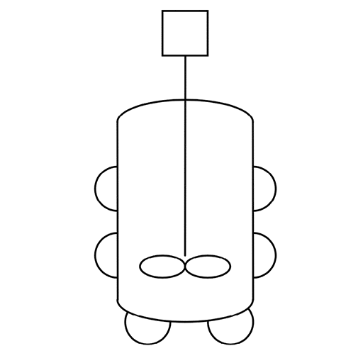
Half-pipe mixing vessel

Agitator or mixer

Dryer
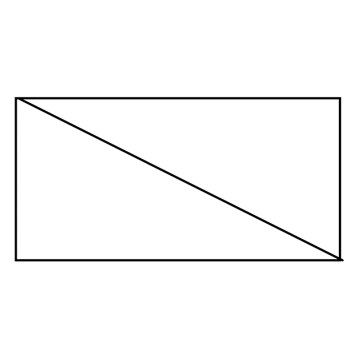
Backdraft damper
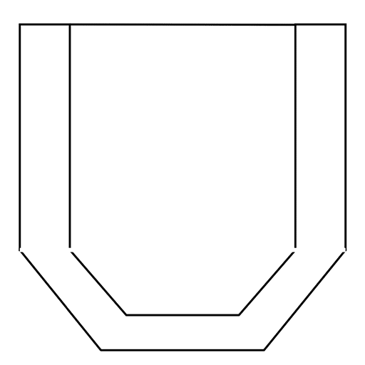
Furnace
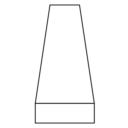
Cooling Tower
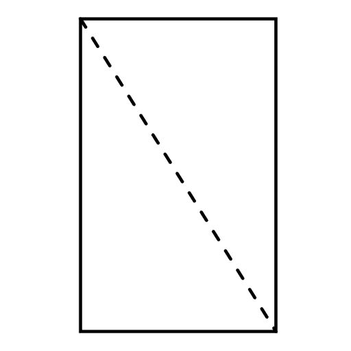
Air filter
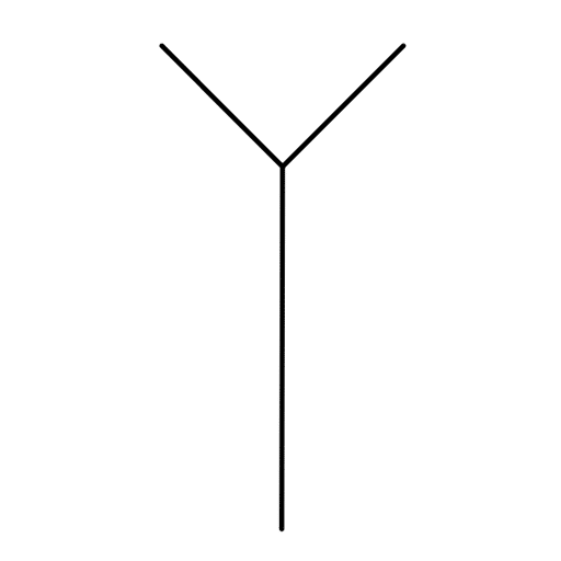
Funnel
Heat Exchanger Symbols
A heat exchanger is a device that’s designed to transfer heat from different medium to another mediums. For example, an airconditor or a radiator in a house. This includes boilers, condensers, and other heat exchangers.
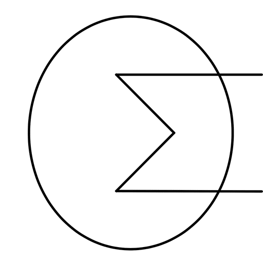
Heat Exchanger
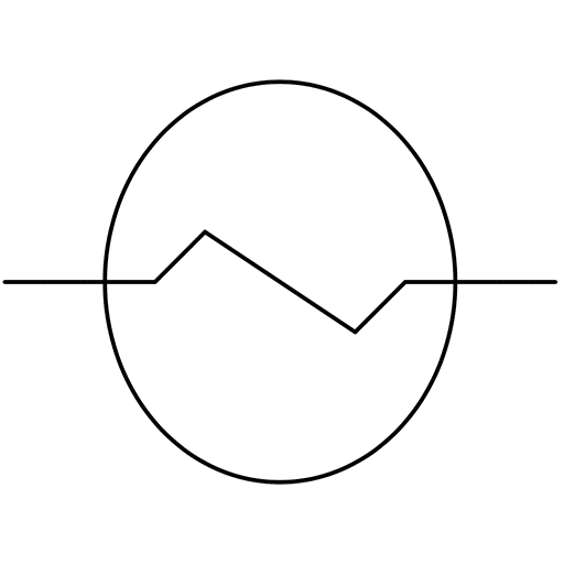
Heat Exchanger
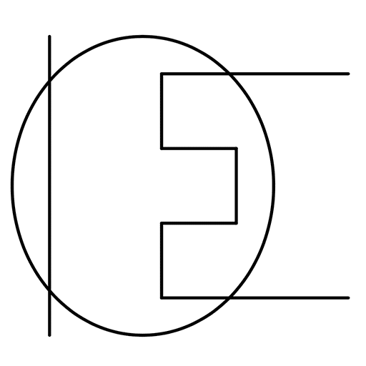
Cooler
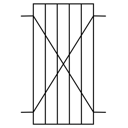
Plate & frame heat exchanger
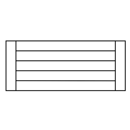
Fixed straight tubes heat exchanger
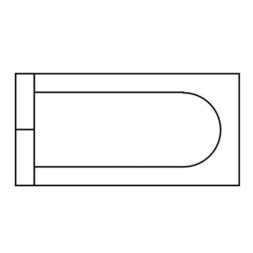
U-shaped tubes heat exchanger
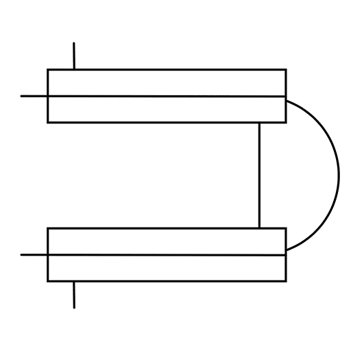
Double pipe heat exchanger
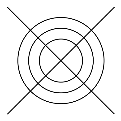
Spiral heat exchanger
P&ID Symbols Abbreviations
P&IDs use a standardized set of notation and abbreviations to represent the various components of a process. These notations are used to indicate the type of fluid, the size, and the pressure rating of the component. These include:
| CT | Conductivity Transmitter |
| CI | Conductivity Indicator |
| CC | Conductivity Controller |
| FL | Flow Transmitter |
| FI | Flow Indicator |
| FC | Flow Controller |
| FS | Flow Switch |
| LT | Level Transmitter |
| LI | Level Indicator |
| LS | Level Switch |
| LA | Level Alarm |
| PT | Pressure Transmitter |
| PI | Pressure Indicator |
| PC | Pressure Controller |
| PRV | Pressure Regulationg Valve |
| PA | Pressure Alarm |
| PC | Pressure Controller |
| TT | Temperature Transmitter |
| TI | Temperature Indicator |
| TC | Temperature Controller |
| TCV | Temperature Control Valve |
| ST | Steam Trap |
| SG | Sight Glass |
| S | Strainer |
| T | Tank |
| P | Pump |
| HX | Heat Exchanger |
| PSV | Pressure Sanitary Valve |
| PUW | Purified Water |
| XV | Actuated Valves |
Further Reading
About the Author
Donagh Fitzgerald
Head of Marketing & Product Development
Mechanical/Production Engineer
Donagh looks after the marketing and product development including the training and pedagogical elements of our programs and makes sure that all GetReskilled’s users can have a great online learning experience. Donagh has lived and worked in many countries including Ireland, America, the UK, Singapore, Hong Kong and Japan. Donagh has also served as the Program Manager for the Farmleigh Fellowship based out of Singapore.
Donagh holds Degrees in Production Engineering and Mechanical Engineering from South East Technological University, Ireland.
Gerry Creaner
President
Senior Lecturer with GetReskilled
Gerry Creaner has over 40-years of experience in the Life Sciences Manufacturing industry across a range of technical, managerial and business roles. He established a very successful engineering consultancy prior to founding GetReskilled, an online education and learning business, with offices in Singapore, Ireland and Boston (USA), focussed on the manufacture of safe and effective medicines for the public.
He is also a founding Director of two Singapore based philanthropic organizations, the Farmleigh Fellowship and the Singapore-Ireland Fund, both of which deepen the well established and historical Singapore – Ireland relationship and deliver long-term benefits to both countries.
Gerry has an undergraduate degree in Chemical Engineering (UCD, 1980) and an MSc (Management) from Trinity College Dublin (2003) and is currently doing research for his Ph.D.

